regl is a technology meant to simplify building awesome things with WebGL. Recently, Mikola Lysenko, one of the creators of regl, gave a great talk at OpenVis Conf that got me wanting to spend more time with WebGL and regl in particular - to see how it could be applied to my data visualization work.
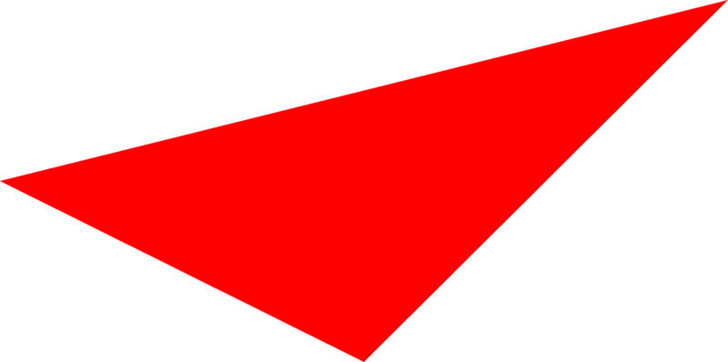
With this tutorial, I hope to share my brief learnings on this wonderfully mystical technology and remove some of that magic. Specifically, how do we make the jump from the interesting but not so applicable intro triangle example:
To using regl for some sort of data visualization? At the end of this tutorial, hopefully you (and I) will find out!
We will start with the triangle. Try to understand WebGL and regl in the context of this example, then work to modify it to expand our understanding. We will cover some basics of WebGL and shaders, setting up your development environment to work with regl, and then explore a subset of regl’s functionality and capabilities.
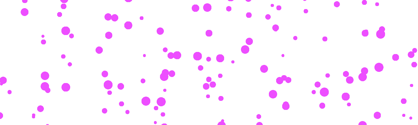
The final result will be a data stream visualization:
This falls short of the amazing regl visualizations Peter Beshai has recently produced and discussed, but hopefully this tutorial can serve as a stepping stone towards this greatness.
And if you want to just skip to the results, I’ve made a bunch of blocks to illustrate the concepts covered:
- Plain regl triangle
- regl triangle in a loop
- regl triangle moving
- regl triangle using props
- Displaying dots with regl
- Data Stream with regl
What is WebGL?
First, it might be useful to step back a bit and talk at a high level about WebGL and regl and what they are good for. If you know all this, feel free to skip ahead.
As the wonderful Mozilla Developer Network so succinctly puts it, WebGL - or the Web Graphics Library - is a way to create interactive 2D and 3D visuals in a web browser with just Javascript. It is a low level API that utilizes the canvas tag, and can be used to make some pretty impressive stuff.
WebGL has a lot going for it. Its supported in many browsers, it can be crazy fast as the code is executed on the GPU, and there are lots of impressive examples to get you started.
But it is also a crazy confusing API for folks just getting started who are not familiar with these types of systems. WebGl is a graphics pipeline that includes a number of steps that are used to get an image rendered to the screen. The API is very low-level and it can take a lot of work just to get something on the screen.
What is regl?
The regl framework simplifies the task of developing WebGL code by providing a more functional interface. It takes cues from the React world, providing a consistent and familiar way to pass state and properties into the WebGL code.
So, you still have to write some WebGL, but the parts that you are responsible for writing are simpler, isolated, and have a defined signature.
Throwing Shade with Shaders
The WebGL code you still need to write are known as shaders. Shaders are functions written in a special C-like graphics language called GLSL or OpenGL Shading Language (OpenGL being the standard WebGL is based on).
There are different types of shaders, specifically two types:
- Vertex shaders
- Fragment shaders
Each type is responsible for configuring a different portion of the WebGL rendering pipeline. You need to implement both to make a complete
A Vertex shader is given each point (vertex) of the thing that is being rendered (triangle, sphere, rabbit, dataset) and its job is to determine the position of each of these vertices in WebGL space. If we ponder this idea from a data visualization / D3 perspective, this is kind of like implementing the most specific d3.scale ever. Each vertex is a data point, and the shader is a scale that maps each input point to a location in space and time for your specific visual.
A Fragment shader deals with the visual display of the things rendered in the WebGL pipeline to the screen. Specifically, they need to set the color for each pixel that is being displayed. (Why is it called a fragment shader and not a pixel shader? Good Question!).
As an aside, shaders are called shaders because fragment shaders are used to control lighting and other special effects when using GLSL in game development.
We won’t go into the details of GLSL in this tutorial, but hopefully the simple shaders we use aren’t too confusing. I’d suggest reading a bit of The Book of Shaders if you haven’t seen GLSL at all before - it provides a nice smooth introduction (though it focuses soley on fragment shaders).
As an aside, The Book of Shaders also has a great shader editor you should check out that includes all sorts of nice features. You can learn more about it here.
Here are some other resources that I shamelessly borrowed from, and might cover these concepts more elegantly than me:
Setting up an Exploration Environment
Before we put our pedals to the metals in implementing these concepts in our very own regl program, let’s take a moment to setup an environment that helps facilitate an exploration of these new technologies in a way that doesn’t incite us to throw our computers into the ocean out of frustration.
My solution to reducing frustration with new technologies is typically to supplement existing tools I like with new features. To this end, I’m going to suggest some Atom plugins to use that could make working with GLSL code easier for you.
But there are many other approaches! Feel free to ignore these recommendations and skip ahead, if you have a different methodology for WebGL development.
Also, I’ve included Blocks for each of the steps in the tutorial - which work without any additional setup - so if you don’t want to setup your coding environment now, you could just start forking those!
Atom Packages for GLSL Fun
Here are the Atom packages I would recommend using as we get started. Each can be installed via Atom’s “Preferences” menu.
First, grab the language-glsl package for some nice syntax highlighting of our GLSL code. Initially our GLSL code will be written inline as strings, but eventually we will write this code in .glsl files, so this package will come in handy then.
Next, you might be interested in the autocomplete-glsl which gives you handy autocompleting of GLSL types and functions. It even provides links to the documentation for each function!
Finally, I never leave home without a linter - and linter-glsl provides nice inline warnings and errors in your code so you can catch them early and (hopefully) avoid hours of glaring angrily at your screen just because you forgot a ‘.’ somewhere (it might still happen though!).
To get the linter working, you need to install glslangValidator - which if you are on a Mac and use homebrew you can do easily:
brew install glslang
A Baseline for good regling
Ok, after far too much yawning, let’s get to some code. Here we will add the necessary JS packages to our development environment - so again skip ahead if you are just working with the Blocks for now. Most of this section is a rehash of the lovely from nothing to something in WebGL blog post by Ricky Reusser - so feel free to use the original source.
First, let’s create a new Javascript project using npm init:
mkdir regl-start
cd regl-start
npm init
You can just hit enter to select the defaults for the project if you like - or tweak them as necessary. This command adds a package.json file to our new regl-start directory. We will use this file to manage the npm packages we will use.
Some Nice-to-have Packages
We will install a few packages to get things up and running quickly. The commands to run inside your project are:
npm install --save regl
npm install --save-dev browserify budo
Here’s a short description of what the development packages provide us:
- browserify is a package that allows us to
requireother javascript modules in the browser (therequirefunction comes from the node world and browserify brings it to the web). - budo is a development web server that works well with browserify and provides auto-reloading your browser every time you make a change to your code. Handy!
The --save-dev flag puts them in the devDependencies of the package.json file. These packages are needed only to develop and build the project.
Starting up with start
Next we need to create our Javascript starting point. Let’s name it index.js:
touch index.js
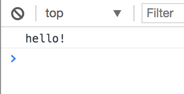
touch is a unix command that creates an empty file if no file exists. Inside our index.js, let’s write a simple test to ensure it is getting loaded (regl-less for now)
console.log("hello!");
Now we need to make browserify and budo work for us to build and serve this script.
Back in the package.json, we have a "scripts" section. Here we will remove the test script for now and add a start script that looks like this:
"scripts": {
  "start": "budo index.js --open --live"
},
This tells budo to browserify our index.js file and open a web browser to view it. The --live indicates to repeat this process any time the code changes.
Let’s run our start script from the command line using npm!
npm start
If everything went correctly, a new browser window should open and we should see our hello in the Console.
Hello Triangle!
Ok, so far that was just a how to get budo and browserify on your machine tutorial - which is fine but not what we promised. So let’s add some regl!
We will start by displaying a triangle which is the first example provided on the examples page - and serves as something like the ‘hello world’ of regl.
Let’s put this in our index.js file, and then go over the details:
const regl = require("regl")();

const drawTriangle = regl({
  // fragment shader
  frag: `
  precision mediump float;
  uniform vec4 color;
  void main () {
    gl_FragColor = color;
  }`,

  // vertex shader
  vert: `
  precision mediump float;
  attribute vec2 position;
  void main () {
    gl_Position = vec4(position, 0, 1);
  }`,

  // attributes
  attributes: {
    position: [[-1, 0], [0, -1], [1, 1]]
  },

  // uniforms
  uniforms: {
    color: [1, 0, 0, 1]
  },

  // vertex count
  count: 3
});

drawTriangle();
(Note the ` around the shader code. They are actually strings passed in to frag and vert).
This draws a triangle:
Hurrah! But how?
Ok, first step is pretty simple. We require regl (remember we are using browserify - so we have that power). On the same line, we are calling the returned function which creates a full screen canvas element. This sets up our canvas and WebGLRenderingContext automatically.
Next we create a regl draw command by calling regl(). As the docs state, draw commands are the main point of the library. They allow for packaging shader code, as well as state and input parameters into a single reusable command.
Minimally, a regl draw command takes an object with a few parameters:
- frag which specifies the fragment shader code (written in GLSL).
- vert which specifies the vertex shader code (again in GLSL).
- count which indicates the number of vertices to draw.
In this example, both shaders are written as one big string (we will see how to improve this setup later). This draw command also provides more parameters: attributes and uniforms which we will look at below.
Now let’s recap the purpose of these two shaders, and look a bit at how they work.
The vertex shader needs to accomplish its goal of positioning each vertex. It is called once for each vertex and needs to set the gl_Position global during each call.
The fragment shader needs to set the color for each fragment. It does this by setting the gl_FragColor global each time it is called.
No matter what else happens in these shaders, these two variables (gl_Position and gl_FragColor) are what need to be set.
Also note the general structure of a shader. You start with the declaration of variables and then use these variables in your shader’s main() function. The precision mediump float; line sets the precision of floating point values.
We run the draw command by calling it on the last line:
drawTriangle();
And a triangle is born!
We can see some of the interactions between regl and shader code - but not everything is immediately clear. For example, we see color listed in uniforms section of the regl command, and then we see uniform vec4 color specified and used in the fragment shader, but what is a uniform?
Let’s talk more about the different variable types in shaders, then come back to see how we work with these in regl.
The Many Shader Variable Types
In shader land, there are three types of variables you can declare. They are all confusing, but I like the explanation provided by html5rocks, so I’ll try to summarize here:
Uniforms are accessible in both the vertex and fragment shader. They are ‘uniform’ because they are constant during each frame being rendered. But (as we will see below), their value can change between frames.
Attributes are only provided to the vertex shader. There is a value for each vertex being displayed. The individual value is provided to the vertex shader when dealing with that specific vertex.
Varyings are variables declared in the vertex shader that can be shared with the fragment shader. We won’t use this in the rest of the tutorial, but its good to know they exist!
regl and Variables
So finally we are getting to what makes regl interesting and worth trying out. How it organizes what you pass in to the fragment shader functions.
Now that we know that uniform and attribute are variable types, I bet you can guess what the uniforms and attributes parameters of the draw command object are for, right? They allow us to specify the values of variables that are accessible in our shaders!
Let’s break it down a bit more.
Our uniforms parameter looks like this:
uniforms: {
  color: [1, 0, 0, 1]
}
This indicates that there will be a color uniform available to the vert and frag shaders. This color variable is a vec4 - a vector of length 4 - as seen in the declaration in the fragment shader, so it is declared here as an array with 4 values.
(Check out the Book of Shaders Color Chapter to learn more about how colors are defined in GLSL).
Our attributes parameter looks like this:
attributes: {
  position: [
    [-1, 0],
    [0, -1],
    [1, 1]
  ]
}
We can see we define one attribute, position, that is an array with 3 values. As we have our count parameter set to 3, the vertex shader code in vert will be run 3 times, each time its corresponding position attribute will be set to the correct value of the position array inside our attributes.
Note that the coordinate system is a bit different then what you might expect. The x and y scales go from -1.0 to 1.0 as shown in this handy diagram from MDN’s WebGL Concepts.

So thats how this triangle gets drawn. Kind of cool, right?
regl Inputs
But wait there’s more!
Currently in this example, the input uniforms and attributes are all static values. But it doesn’t have to be this way!
A big feature of regl is that you can supply inputs to regl through a number of different ways.
To see some of these benefits, let’s convert our triangle from a frame that is displayed just once, to a visual that is displaying over and over through time.
A Triangle In Time
Currently our triangle is rendered in one shot. It is displayed and then it is done. In order to see the benefits of dynamic data, we want to render this triangle over and over again so we can pass in different value each render.
Looping can be done in many ways, but regl provides regl.frame for just such a purpose. This allows us to call our drawTriangle draw command inside a requestAnimationFrame().
Let’s modify our code to use it!
Change our call to drawTriangle() to this:
regl.frame(function(context) {
  drawTriangle();
});
Now, our browser should reload, and we should see our triangle again. In fact, it should look exactly the same.
The difference is that drawTriangle() is now being called over and over again in a loop. We can verify this by console logging a value in context. Try tweaking the regl.frame call to this:
regl.frame(function(context) {
  console.log(context.tick);
  drawTriangle();
});
In the Console, you should see our tick count. And it should be increasing!
(I would remove that console.log after verifying that it is indeed looping - cause it clogs up the Console and slows things down).
The context variable is something that regl populates with a few values. Let’s return back to regl and talk about the ways it allows inputs to the draw commands.
regl Inputs: Context, Props, and this
So we have learned that a core feature of regl is handling inputs to our shaders. We know that shader variables come in 3 flavors: uniforms, attributes, and varyings. And while the triangle example we have been working with deals with static versions of these inputs, I indicated that dynamic inputs were also possible. So lets’ find out how!
regl allows for inputs to its draw commands to come from 3 possible sources:
Context: Context variables are state accessible between child draw commands (which we won’t look at here). It is also the place where regl keeps a number of variables you might find useful - including tick and time.
Props: Props are the most common way to pass in data to a regl draw command. You can pass them in as an input object when you call the draw command.
this: The this variable can be used to save state within a regl command. We won’t look more into this here - but something to keep in mind.
If you are familiar with React, as the regl documentation states, you can use this knowledge to better understand these input options.
- regl’s Context is analogous to React’s Context
- regl’s Props is similar to React’s Component Props.
- regl’s
thisparallels a Component’s State in React.
But how do you use these regl inputs in your draw command?
Well it turns out that, similar to D3 attr, the values of uniforms and attributes properties in regl can be specified using functions! And these functions get access to the context and props of the draw command.
Pretty cool! Let’s try this out.
Flying Triangle
Let’s use our knowledge of the context.tick variable and base our vertex position attribute values on its current value. To do this, we will change position to use a callback function. This function is called inside regl to set the ultimate value of the attribute on each render. This callback function receives the context and props for the draw command (not unlike having access to the bound data for an element when setting an attr in D3).
Modify the attributes portion of your draw command to look like this:
attributes: {
  position: function(context, props) {
    return [
      [-1 * Math.cos(context.tick / 100), 0],
      [Math.sin(context.tick / 100), -1],
      [Math.sin(context.tick / 100), 1]
    ];
  }
},
And our triangle should start flying around on the screen!

Its interesting to note that we made no changes to our shader code to make things dynamic. Instead, we simply put our draw command in a loop (using regl.frame) and then took advantage of regl’s input capabilities to make it dynamic.
Note that while I passed in props to the callback function, we didn’t actually use it - but I wanted to show that this object is also accessible. Let’s look at using this next!
Flying Triangle with Props
The regl documentation states that Props are the most common way to pass data into draw commands, but it doesn’t exactly say why.
With a bit of that React knowledge, and some sample code examination, we can see that a draw commands Props are passed in to it when calling the draw command function.
So, for example, if instead of using a static value for color we wanted to pass in a color Prop to our drawTriangle, we could do so by changing the call to the function like so:
drawTriangle({
  color: [0.208, 0.304, 1.0, 1.0]
});
(I used the Book of Shaders Editor to pick out a nice blue).
And then we can use this color prop in our uniforms:
uniforms: {
  color: function(context, props) {
    return props.color;
  }
},
Now your triangle should be moving, and blue!

(Click on the Block link to see the animation).
If you like shortcuts, regl also provides a handy shorthand notation for accessing props: regl.prop(). Rewriting the above uniforms to use this shorthand would look like:
uniforms: {
  color: regl.prop('color')
},
From Triangles to Dots
Hopefully now we know a bit more about how shaders and regl fit together. We’ve learned about context and props which point to ways to get data into WebGL via regl to visualize.
Let’s move past the triangle and start using this wisdom on some dot data vis.
Displaying Points with regl
The first thing I want to cover is the minimum set of changes we need to convert the drawTriangle draw command into a drawDots draw command.
Here is the full code to get us started (which should look very similar to our triangle code for now). Below we will go over the changes.
const regl = require("regl")();

const drawDots = regl({
  frag: `
  precision mediump float;
  uniform vec4 color;
  void main () {
    gl_FragColor = color;
  }`,

  vert: `
  precision mediump float;
  attribute vec2 position;
  // @change acquire the pointWidth uniform
  //  this is set by the uniforms section below
  uniform float pointWidth;

  void main () {
    // @change Set gl_PointSize global to
    //  configure point size
    gl_PointSize = pointWidth;
    gl_Position = vec4(position, 0, 1);
  }`,

  attributes: {
    position: function(context, props) {
      // @change I tweaked the constants here so
      //  the dots are not off the screen
      return [
        [-1 * Math.cos(context.tick / 100), 0.2],
        [Math.sin(context.tick / 100), -0.8],
        [Math.sin(context.tick / 100), 0.8]
      ];
    }
  },

  uniforms: {
    color: function(context, props) {
      return props.color;
    },
    // @change: Add a pointWidth uniform -
    //  set by a prop
    pointWidth: regl.prop("pointWidth")
  },

  count: 3,
  // @change: Set our primitive to points
  primitive: "points"
});

regl.frame(function(context) {
  drawDots({
    color: [0.208, 0.304, 1.0, 1.0],
    // @change: Pass in the pointWidth prop
    pointWidth: 10.0
  });
});
Load this up and you should have 3 dots moving about the screen.

(The points are hard to see - click on the Block link to see the animation).
So what changed?
The smallest but most important change is near the bottom of the drawDots draw command. We need to switch the primitive type to "points" in our regl setup:
primitive: "points";
This tells WebGL which primitive type to use in the display.
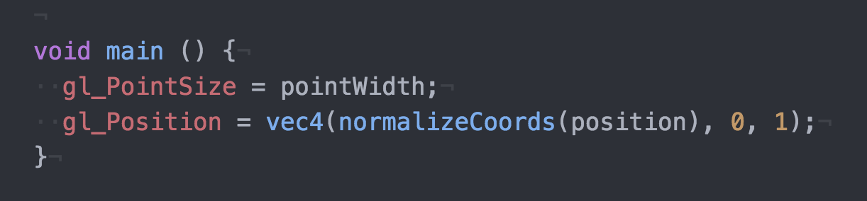
The other main change is that we need to specify a value for gl_PointSize in our vertex shader. We could hard code this value, but its more fun - and more flexible - to use our regl props knowledge to pass it in as a prop. Hopefully you can follow along with the @change comments to see this input setup in the code.
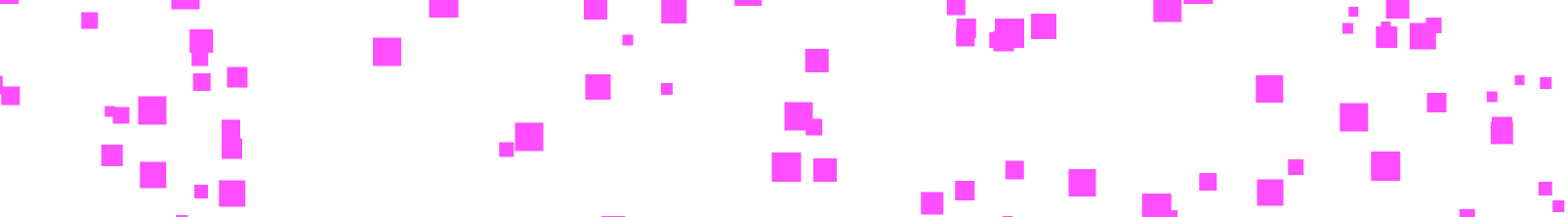
Dots Representing Data
OK! we are coming to the end of the road. We now have dynamic dots, but what we really want is data-driven dots, right?
So using our regl knowledge, we are going to pass in some dynamically generated data and get regl displaying it!
Pretend, if you will, we have a dynamic dataset that represents some collection of values over time. Maybe its car speeds on a length of road, or download speeds for a set of computers, or something more exotic. Probably not the most common of datasets - but what can you do.
Pretend some more that you might want to create an ambient streaming “data vis” to represent this data. Different nodes will move at different speeds and have varying sizes. I write data vis in quotes as this is still a bit of a stretch in terms of something useful - but at least its a start in mapping data to visual attributes with regl.
So, hopefully you have some inklings on how you might accomplish this, given what you know about regl so far. Essentially, we are going to take our drawDots draw command and expand it to use more then three vertices. In fact, our vertices will be controlled by data passed in as Props to the draw command.
Here is the final code block:
const regl = require("regl")();

// Helper function to create a random float between
// some defined range. This is used to create some
// fake data. In a real setting, you would probably
// use D3 to map data to display coordinates.
function randomFromInterval(min, max) {
  return Math.random() * (max - min + 1) + min;
}

// Helper function to create a random integer between
// some defined range. Again, you would want to use
// D3 for mapping real data to display coordinates.
function randomIntFromInterval(min, max) {
  return Math.floor(randomFromInterval(min, max));
}

// Some constants to use
var MAX_WIDTH = 2000;
var MAX_HEIGHT = 800;
var MAX_SPEED = 25;
var POINT_SIZE = 10;
var POINT_COUNT = 400;

// Helper function to generate some fake data.
// Each data point has an x and y and a 'speed'
// value that indicates how fast it travels
function createData(dataCount) {
  var data = [];
  for (var i = 0; i < dataCount; i++) {
    var datum = {
      id: i,
      speed: randomFromInterval(1, MAX_SPEED),
      y: randomIntFromInterval(POINT_SIZE, MAX_HEIGHT),
      x: 0,
      size: randomIntFromInterval(POINT_SIZE, POINT_SIZE * 3)
    };

    data.push(datum);
  }
  return data;
}

// Helper function, goes through each
// element in the fake data and updates
// its x position.
function updateData(data) {
  data.forEach(function(datum) {
    datum.x += datum.speed;
    // reset x if its gone past max width
    datum.x = datum.x > MAX_WIDTH ? 0 : datum.x;
  });
}

const drawDots = regl({
  frag: `
  precision mediump float;
  uniform vec4 color;
  void main () {
    gl_FragColor = color;
  }`,

  vert: `
  precision mediump float;
  attribute vec2 position;
  attribute float pointWidth;

  uniform float stageWidth;
  uniform float stageHeight;

  // helper function to transform from pixel space to normalized
  // device coordinates (NDC). In NDC (0,0) is the middle,
  // (-1, 1) is the top left and (1, -1) is the bottom right.
  // Stolen from Peter Beshai's great blog post:
  // http://peterbeshai.com/beautifully-animate-points-with-webgl-and-regl.html
  vec2 normalizeCoords(vec2 position) {
    // read in the positions into x and y vars
    float x = position[0];
    float y = position[1];

    return vec2(
      2.0 * ((x / stageWidth) - 0.5),
      // invert y to treat [0,0] as bottom left in pixel space
      -(2.0 * ((y / stageHeight) - 0.5)));
  }

  void main () {
    gl_PointSize = pointWidth;
    gl_Position = vec4(normalizeCoords(position), 0, 1);
  }`,

  attributes: {
    // There will be a position value for each point
    // we pass in
    position: function(context, props) {
      return props.points.map(function(point) {
        return [point.x, point.y];
      });
    },
    // Now pointWidth is an attribute, as each
    // point will have a different size.
    pointWidth: function(context, props) {
      return props.points.map(function(point) {
        return point.size;
      });
    }
  },

  uniforms: {
    color: function(context, props) {
      // just to be a bit strange, oscillate the color a bit.
      return [Math.cos(context.tick / 100), 0.304, 1.0, 1.0];
    },
    // FYI: there is a helper method for grabbing
    // values out of the context as well.
    // These uniforms are used in our fragment shader to
    // convert our x / y values to WebGL coordinate space.
    stageWidth: regl.context("drawingBufferWidth"),
    stageHeight: regl.context("drawingBufferHeight")
  },

  count: function(context, props) {
    // set the count based on the number of points we have
    return props.points.length;
  },
  primitive: "points"
});

var points = createData(POINT_COUNT);

regl.frame(function(context) {
  // Each loop, update the data
  updateData(points);

  // And draw it!
  drawDots({
    pointWidth: POINT_SIZE,
    points: points
  });
});
And this makes a data stream!
Take a look and see if it makes any sense (and let me know if it doesn’t!). I’ve added some helper functions to generate fake data. Each datum is an object with x, y, speed, and size attributes.
The main difference between our previous three-dotted visual and this one is that we are passing in the points data as a Prop, and using this array to derive uniforms and attributes.
As a quick example, here is how the position attribute is now created:
position: function(context, props) {
  return props.points.map(function(point) {
    return [point.x, point.y]
  });
},
So, this makes an array of arrays, with each inner array containing the x and y value from our points. As before, the vertex shader will be called once for each point in the points data (thanks to our modification to count) and the position for that particular vertex will be set by its corresponding position entry.
The other trick in this code is that the vertex shader has a helper function to convert our data x and y values into WebGL coordinate space. This was stolen right out of Beshai’s tutorial, so you will have to read that to find out more.
You’ll notice we are still using the CPU (code outside of a shader) to handle positioning the data values. Wouldn’t it be great if we could do that on the GPU as well? Turn in next week when we attack this critical issue!
GLSLify Your Life
One last thing! So far we haven’t gotten a chance to use all those Atom packages or that linter I made you install. What gives?
Well, to simplify the generation of the blocks, I decided to keep all the GLSL shader code as strings - like you see in most of the regl examples.
But do you like coding complex C-like languages in strings?? Me neither.
So with one additional package, we can throw off the chains of shader strings and feel the warm embrace of better development tools. Trust me? Ok, let’s do it.
Return, if you will, to your command line and install the glslify package:
npm install --save-dev glslify
What is glslify? Two things:
- A way to import glsl code from a
.glslfile so you don’t have to write shaders as giant strings. - A mechanism that allows you to import glsl code that other people have written - so you can use them in your own shaders. This provides a sort of NPM for shader code (which is a pretty cool idea).
We will focus on the first of glslify’s abilities, but I hope to get to experiment with existing glsl packages soon.
In order to enable glslify in our development environment, we need to tell browserfiy to use it as a transform when processing our scripts. We can do this in our package.json by adding a new browserify section:
"browserify": {
  "transform": [
    "glslify"
  ]
}
Now we are ready to extract our GLSL code into their own files.
To do this you can create a sub-directory in your project (I called it shaders) and here create two files:
shaders/draw_dots.fs.glslshaders/draw_dots.vs.glsl
The fs will store our fragment shader, and the vs will store our vertex shader.
We can pretty much copy and paste over the shader code out from the strings in index.js and into these new files (don’t copy over the string ticks - just the code inside them).
If you installed all those packages I told you about, you should see syntax highlighting and linting in these files. Pretty cool right?
To import these shader files back into index.js, use glslify:
// import glslify at the top
var glslify = require('glslify');

// ...

// use glslify to import shader code!
regl({
  frag: glslify('./shaders/draw_dots.fs.glsl'),
  vert: glslify('./shaders/draw_dots.vs.glsl'),
  // ...
});
I’ve made a little starter repo that has this all setup in it, if you’d like to start with it for your explorations:
Go Forth you regl Beings
That’s all I have on my experiences with regl. If this piqued your interests and you want to go further - or if this was too boring an intro - be sure to check out Peter Beshai’s Beautiful regl Point Animations. Hopefully, though this tutorial does repeat a bit of his (and hey its good to repeat things sometimes), they work together to provide an intro and exploration of point visualizations in regl.
There is plenty more to explore! As always, be sure to share your regl experiences or questions in a regal manner in the comments or @vlandham on Twitter.
Bonus: Circle Points
Just in case your next comment is “great, but how do I make these points circles?”, I’ve got you covered!
Check out this block.